Final Project _INTERACTIVE DAISY
CONCEPT AND DESIGN
Phylotaxis
Its structure, derived from the Fibonacci Sequence and closely related to the Golden Ratio, is one of nature's most elegant. The Fibonacci Sequence is the set of numbers where each number is the sum of the previous two numbers. This simple sequence governs phenomena as diverse as the petal arrangement of roses, the breeding patterns of rabbits, and the shape of our galaxy. It is also evident in the design of the Great Pyramids, the composition of the Mona Lisa, and the construction of Stradivarius violins.

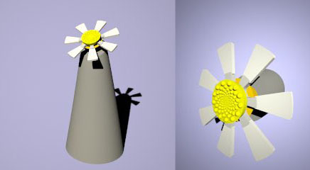
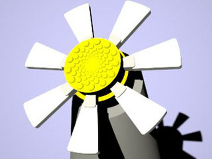
Renders
PROCESS_See class 19, here there are some examples of previous test and ideas before geting the last one done.
The project was meant to be a system with different components, the purpose of the installation was to interact with people.
In order to be able to complete the exercise I have decided to do just one component ( daisy)
To be able to practise all the exercises we have done during the FAB Academy course I have design the flower to be built in all the different machines at the lab.
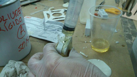
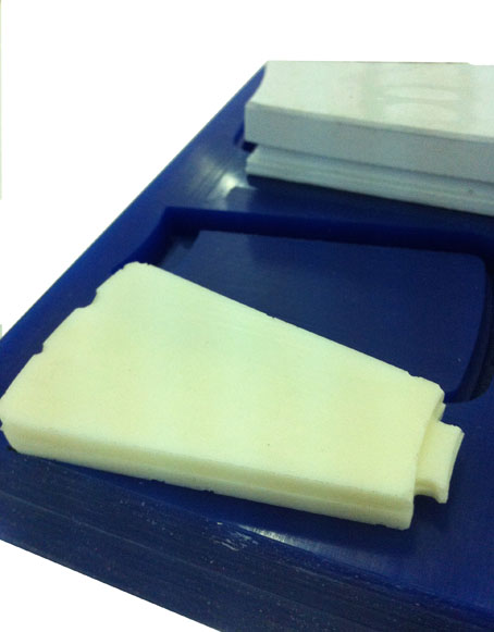
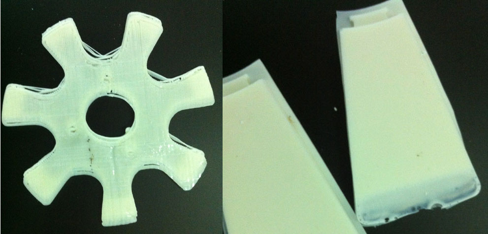
1_Petals_ Milling a wax mold and then producing 7 petals with rigid poliuretano
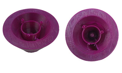
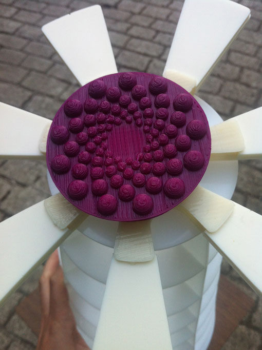
2_Flower Heart_ I have model the piece in rhino and used the maker boot to 3D printed the final piece, that it has being built in 2 parts.
3_Cuore_ Phylotaxis
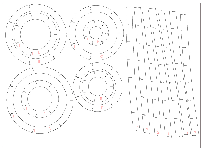
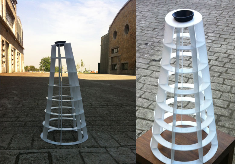
4_Vase_ I have also model the vase in rhino and then i have extract the wireframe and extrude the curves, The final material is white acrylic 2 mm thickness, but I have tried also a black acrylic 3 mm and plywood, there are some images that shown why it did not work. See class 19
The most difficult part it has being to get to a design that allows the electronics to work.
At the beginning I was concerned about the design but I have forgotten that the motor rotates and needs to leave a space to maintain the power cables stable and still be able to move the rest.
Since in the design there are 3 main parts
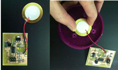
1_Phylotaxis _where the piezo and the electronics are placed,
2_The heart that keeps inside the petals and also the white led lights.
3_The piece that allows the flower to lay on top of the acrylic vase structure.
FABRICATION FILES
MOLDS_
3D PRINITING FILES
Daisy_heart.stl, Motor base.stl, Phylotaxis.pistil.stl
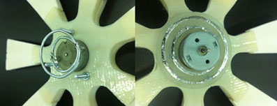
TESTING THE ROTATION MANUALLY
I have first put the petals inside the flower heart in order to see how the hole piece rotate together, and as we can see in the video the rotation is quite good.
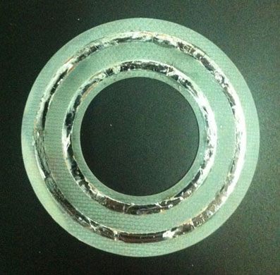
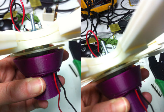
HOW TO TRANSMIT THE MOVEMENT TO THE PIECE_
One of the difficulties I have found was how to transmit the movement from the motor to the main piece, and do not roll the power cables.
I have come out with this idea: It is a milled PCB, with 2 concentric circles, that will allow the cables to be in contact all the time without loosing the connection and without moving.
VIDEO
TEST 2
I could not make it work, the motor seems to be excentrical and the power cable does not rotate equally.
ELECTRONICS
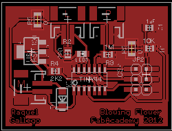
I have used the hello motor board from the output exercise, and I have added 2 more connectors one for the motor and the other one for the piezo. I have then 3 connectors, LED, MOTOR, PIEZO.
BOARD
This is the final board with all the components.
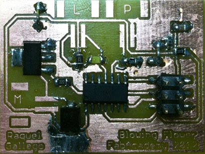
TEST
THE PCB is working !!!

Blowing system.br, Blowing system.sch, Blowing_system.png,Blowing system.ps
CODE_ Since I have not being able to make the motor work. The code has been programm in arduino and what it does is read the piezo and react to it lighting up a LED.
// In order to connect the piezo to the analog input we need to add a big resistor
// to limit the current that can be produced with a big knock.
//             1M
//   GND --+-/\/\/\/-+-- Analog 0
//         |         |
//         +--PIEZO--+
//

#define LED_PIN 8
#define PIEZO_PIN 3
#define MOTOR_PIN 2
#define FADE_TIME 20

void setup()
{
  pinMode (LED_PIN ,OUTPUT);
  // as the LED is inverted (cathode to attiny pin), we set the pin high for turn it off
  digitalWrite(LED_PIN, HIGH);
}


void fade_in_led()
{
  int i;
  for (i=0;i<=FADE_TIME;i++)
  {
    digitalWrite(LED_PIN, LOW);
    delay(i);
    digitalWrite(LED_PIN, HIGH);
    delay(FADE_TIME-i);
  }
  digitalWrite(LED_PIN, LOW);

}

void fade_out_led()
{
  int i;
  for (i=0;i<=FADE_TIME;i++)
  {
    digitalWrite(LED_PIN, LOW);
    delay(FADE_TIME-i);
    digitalWrite(LED_PIN, HIGH);
    delay(i);
  }

}

void loop()
{
  int piezoValue;

  piezoValue = analogRead(PIEZO_PIN); // Reading the analog value from analog Port 1 (RX on the ftdi connector)

  if (piezoValue>20)
  {
    fade_in_led();
    delay (2000);
    fade_out_led();
  }


}
TEST PIEZO
FABRICATION PROBLEMS
The motor part was very difficult to get it work, it may be because I work with rhino, and sometimes the 3d printer interpretates the surface in a different way.
in order to be abe to keep working and run some test with the motor on, I just printed the interior piece and pace it in the other one.
FINAL MODEL
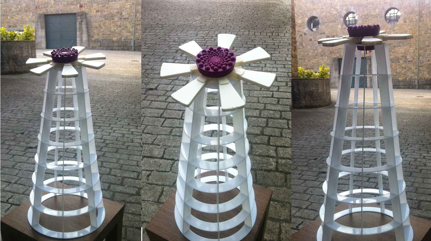
IMAGES
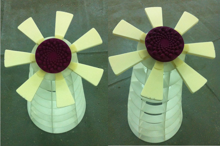
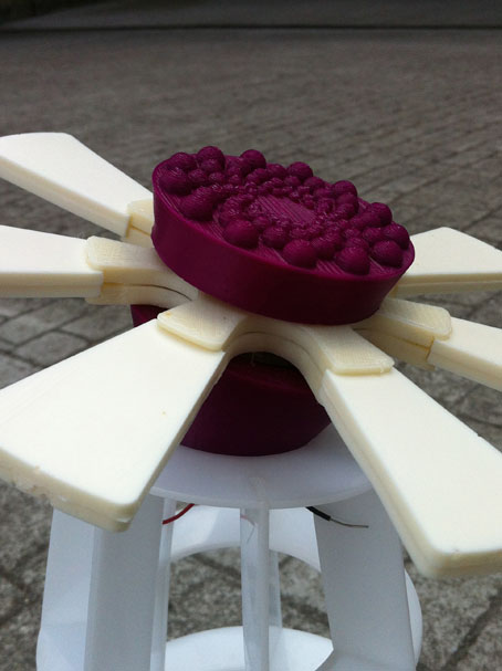
This is the complete piece, I have to continue until I get the motor running.
The inicial idea was to produce a product and give people two options one under the creative commons license. And the other one when I will get the product working, since I have not being able to finish it yet I will complete this part when I get the daisy working.But basically I think it could be sold as a kit.
FINAL VIDEO
1 HOUR BEFORE THE PRESENTATION
Thinking in the slots cars system, Instead of using normal cable, I have soldered a piece of desoldering braid, and because it is wider than the cables it is WORKING!!!!
CREATIVE COMMONS LICENSE

This work is licensed under a Creative Commons Attribution-NonCommercial-ShareAlike 3.0 Unported License.